AUSPOS - Online GPS Processing Service
Page last updated:19 August 2024
AUSPOS is an openly available online GPS data processing service provided by Geoscience Australia. It takes advantage of both the International GNSS Service (IGS) Stations Network and the IGS product range, as well as the Asia-Pacific Reference Frame Network (APREF) station data and coordinate solutions. AUSPOS works with data collected anywhere on Earth.
You can submit dual-frequency geodetic quality GPS RINEX data observed in a 'static' mode to AUSPOS, and an AUSPOS report will be emailed to you with the Geocentric Datum of Australia 2020 (GDA2020), Geocentric Datum of Australia 1994 (GDA94) and International Terrestrial Reference Frame (ITRF) coordinates.
AUSPOS Submission checklist
Before submitting your GPS RINEX file/s, please note:
- AUSPOS provides a network solution (relative positioning) using a double-difference strategy.
AUSPOS does not use the Precise Point Positioning (PPP) computation strategy.
Dual-frequency measurements from GPS L1 and L2 signals are required. Measurements from all other GNSS constellations, including Galileo (E). Beidou (C), GLONASS (R), QZSS (J), are ignored during processing. - Ensure each RINEX file submitted contains at least one hour of observations. Centimetre level position estimates are more likely to be achieved with 6+ hours of static observations.
- Ensure all RINEX files submitted in the same job contain an overlapping period of more than one hour. Otherwise, submit files individually as different jobs.
- DO NOT submit measurements for the current UTC day. Please wait until the next UTC day after 0300 (3 am) UTC time. This allows the RINEX files of reference stations to be downloaded for the current UTC day.
- DO NOT submit receiver raw binary files (for example files with extension: M00, T01, T02, DAT, SBF, TPS...).
- ONLY submit RINEX observation "O" files. DO NOT submit RINEX files with extensions: "N", "M", "G", "L", "P", "H".
- RINEX filenames should NOT contain any special characters, symbols or spaces (e.g. " * ", " _ ", " - ").
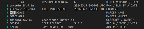
- The station name will be read from the first 4 letters of the "MARKER NAME" line in the RINEX header. An example RINEX header is below.
- Ensure the interval (INTEGER only) of measurements is equal to or bigger than ONE second. It is better to have all RINEX files with the same interval. AUSPOS will sample all RINEX files to 30 second intervals.
- DO NOT use special characters for "MARKER NAME" and "MARKER NUMBER" in the RINEX header. ONLY use numbers and/or letters from the modern English Alphabet.
- After the "END OF HEADER" line in the RINEX header, only observation data should be present (Epoch time and Measurements). Please check before submission.
- AUSPOS uses a priority list for the observations included in the RINEX file. This priority list translates to the below:
For RINEX version 2:
L1 frequency carrier phase: L1
L2 frequency carrier phase: L2
L1 frequency pseudo-range: P1 C1
L2 frequency pseudo-range: P2 C2
For RINEX version 3 (and version 4):
L1 frequency carrier phase: L1P L1W L1C L1X
L2 frequency carrier phase: L2P L2W L2C L2D L2X
L1 frequency pseudo-range: C1P C1W C1C C1X
L2 frequency pseudo-range: C2P C2W C2C C2D C2X
For each RINEX file, please ensure that there is at least one observation type for each of the two frequencies and for both carrier-phase and pseudo-range measurements. - For a RINEX v2 file, if BOTH C1 and P1 (C2 and P2) code measurements exist, P1 (P2) is given priority to be processed. In this case, please ensure all GPS satellites contain P1 (P2) measurements.
- For a RINEX v2 file, if only C1 (C2) code measurements exist, please ensure all GPS satellites contain C1 (C2) measurements.
- For RINEX v3 (and v4) files, C2S (code measurement) and L2S (phase measurement) from L2 frequency will NOT be accepted.
- For RINEX v3 (and v4) files, the accepted measurements from L1 frequency are currently C1P and L1P; C1W and L1W; C1C and L1C; and C1X and L1X.
- For RINEX v3 (and v4) files, the accepted measurements from L2 frequency are currently C2P and L2P; C2W and L2W; C2C and L2C; C2D and L2D; and C2X and L2X.
- If RINEX files are Hatanaka compressed, please use the lower case "d" for the filename extension.
AUSPOS submission
Frequently asked questions
Question 1.1 - What is AUSPOS - Online GPS Processing Service?
- AUSPOS is a free online GPS data processing service provided by Geoscience Australia
- AUSPOS takes advantage of both the IGS Stations Network and the IGS product range, and works with data collected anywhere on Earth
- Users submit their dual frequency geodetic quality GPS RINEX data observed in a 'static' mode to the AUSPOS GPS data processing system
- An AUSPOS report will be emailed to you (typically in less than ten minutes) containing Geocentric Datum of Australia 2020 (GDA2020), 1994 (GDA94) and International Terrestrial Reference Frame (ITRF) coordinates
Question 1.2 - Who can benefit from the service?
The service aims to assist a variety of users from the private and public sector who require coordinates in the Australian Datum (Geocentric Datum of Australia 1994/2020) and/or International Terrestrial Reference Frame (ITRF) coordinates. This includes people undertaking surveys such as:
- Reference station positioning
- Remote GPS station positioning
- Ultra-long GPS baseline positioning
- GPS connections to IGS and ARGN and APREF stations
- High accuracy vertical GPS positioning
- GPS network quality control
Question 1.3 - What do I need?
All you need to submit your data and receive your report is:
- Geodetic quality dual frequency GPS receiver observation data in RINEX format
- Access to a web browser with an Internet connection
- An email account
All the GPS data processing occurs in the AUSPOS GPS data processing server, so the type and capability of your computer is NOT important.
Question 1.4 - What do I submit?
- GPS RINEX observation data (navigation data is NOT required);
- the GPS antenna type;
- the GPS antenna height; and
- your email address.
The GPS antenna type and height can be either provided by the user or extracted from the RINEX file header using the “Scan” button once the RINEX file is uploaded. If scanning the RINEX file, ensure this information is correct in the header of the file.
Question 1.5 - How do I get the results?
The results are emailed to you when the processing is complete. Hyperlinks are also provided to download the reports and relevant result files. If you are having trouble accessing either of these, please contact us at clientservices@ga.gov.au
Question 1.6 - How fast is it?
This depends on how much data you have submitted. A single site with one day of data should be completed within about ten minutes. A multiple site solution might take up to and over twenty minutes. The processing times depend upon system load.
Question 1.7 - How much does this service cost?
There is no cost.
Question 1.8 - What happens to my RINEX files?
AUSPOS will retain your RINEX files for seven days only and will then discard the data.
AUSPOS will NOT retain a copy of your data set beyond 7 days or release any submitted data sets to anyone.
Question 1.9 - Does AUSPOS process real time or kinematic data?
The service does NOT process real time, kinematic, or single frequency GPS data.
Question 1.10 - Does AUSPOS process GLONASS or Galileo data?
The service does NOT process non-GPS data, however; if GNSS data is in the RINEX file it will just be ignored.
Question 1.11 - Why do we make the service free?
AUSPOS provides the service freely to encourage consistency of all precise coordinates used by the GPS community. By making the service free, the Australian GPS community can better compete for contracts throughout the world. Feedback from Australian private sector survey firms show positive support for the service. They are competing internationally for contracts using the AUSPOS service as an important selling point. Effectively, every small survey/GPS organisation in Australia now has access to a very sophisticated GPS data processing system.
Question 2.1 - How does AUSPOS work?
All computations are undertaken using the Bernese Software. Bernese is a high precision orbit and geodetic parameter determination software system. For more information see Bernese GNSS Software.
The International GNSS Service (IGS) product range is used in the computation process. Precise orbit parameters, Earth orientation parameters and coordinate solution IGS products are used.
NOTE: The IGS final orbit product is not available until approximately two weeks after the observation day. The rapid orbit product is available two days after observation, and is used if the IGS final orbit product is unavailable. If both the final and rapid orbit products are unavailable, then the IGS ultra-rapid orbit product will be used.
Once a user has submitted a RINEX file, the nearest 15 IGS and APREF stations are used as the reference stations for the processing. That data is retrieved from Geoscience Australia's GNSS Data Archive. A precise solution using a 'double difference' technique is then computed using these stations. The coordinates of the IGS stations are constrained with uncertainties of 1 mm for horizontal and 2 mm for the vertical.
Question 2.2 - How are observational errors accounted for?
The effects of observation error sources, such as receiver clocks, troposphere and ionosphere are taken into account, either through modelling, or estimation of related parameters. All the computations are undertaken according to IERS conventions.
A summary of the computation standards are provided as an appendix to all processing reports.
Question 2.3 - Does AUSPOS work with data collected anywhere on Earth?
Yes, AUSPOS is designed to work anywhere on Earth because the IGS Stations Network has global coverage. We download all IGS core station data and the APREF station data as soon as they are available in the Geoscience Australia GNSS data archive.
Question 3.1 - When was AUSPOS upgraded to version 3.0 and what was the purpose of this upgrade?
AUSPOS was upgraded to version 3.0 on 13/08/2024. Moving from AUSPOS v2.4 to AUSPOS v3.0 was an essential upgrade that aligns the AUSPOS coordinates to the most recent International Terrestrial Reference Frame (ITRF2020) and its IGS realisation (IGS20/igs20.atx). AUSPOS v3.0 uses the most reliable and most up to date IGS20 products. IGS14 products (used by AUSPOS v2.4 – aligned to ITRF2014), are no longer maintained by the IGS.
Question 3.2 - Should I expect the same coordinates from AUSPOS v3.0 compared to AUSPOS v2.4? Why are my GDA2020 coordinates from AUSPOS v3.0 slightly different to my GDA2020 coordinates for the same site from AUSPOS v2.4? Which coordinates should I use?
We have carried out extensive assessments to confirm that the GDA2020 coordinates from AUSPOS v3.0 are mainly consistent with the coordinates from AUSPOS v2.4. We have confirmed that for most solutions users should expect only small differences in the GDA2020 coordinates (millimetre level for horizontal coordinates and less than 1 cm level for height), with almost all differences within the positional uncertainty levels (and therefore statistically insignificant).
There are many reasons why GDA2020 coordinate output from AUSPOS v3.0 might be slightly different to those output from AUSPOS v2.4.
In AUSPOS v3.0, the coordinates and velocities of the reference stations (used for selection of the reference sites and their a priori coordinates in the AUSPOS network calculation) are aligned to IGS20/igs20.atx and contain coordinates up until 2022. AUSPOS v2.4 used reference coordinates and velocities that were aligned to IGb14/IGb14.atx (IGS realisation of ITRF2014) and only contained coordinates up until 2020. This change in the reference coordinate files may lead to differences in network selection (which in turn can lead to differences in network geometry), baseline lengths and reference site coordinates. All these factors may change the final solution slightly.
Several other changes were made to the IGS products with the update to IGS20, which in turn could induce small changes in the estimated coordinates (see [IGSMAIL-8238]). Some of these changes include:
- the processing of Galileo observations, in addition to GPS and GLONASS, by a number of IGS Analysis Centers,
- updated satellite antenna calibrations,
- the adoption of the new IERS secular pole model,
- the rotation of phase centre corrections to the actual orientations of antennas not oriented North,
- updated post-seismic deformation models,
- updated station coordinate discontinuities and offsets,
- and updated ground antenna calibrations.
Updates to the ground antenna calibration values for some antenna types (e.g., TRM55971.00) have been applied in the IGS20/igs20.atx frame (including changes in the antenna calibration files igs20.atx and ngs20.atx). These updates may cause differences of up to a few centimetres mainly in the AUSPOS Ellipsoidal Height components. This is a direct result of the changes to the antenna files used by each AUSPOS system.
It is important to consider the positional uncertainty of the AUSPOS solution (95% C.L) when comparing coordinates produced by AUSPOS v2.4 and AUSPOS v3.0. GA recommend that users consider AUSPOS v3.0 solutions as superior to AUSPOS v2.4 solutions – simply because AUSPOS v3.0 uses the most up to date and reliable IGS products in the calculations.
Question 3.3 - How does AUSPOS v3.0 calculate GDA2020 coordinates? And how is this process different to how AUSPOS v2.4 calculated GDA2020 coordinates?
Since AUSPOS v3.0 produces coordinates aligned to ITRF2020, a two-step approach must be applied to propagate ITRF2020 coordinates to GDA2020, according to the GDA2020 Technical Manual published by the Intergovernmental Committee on Surveying and Mapping (ICSM). ITRF2020 coordinates are transformed to ITRF2014 using the 14-parameter conformal transformation using the official set of parameters published by the International Earth Rotation and Reference Systems Service (IERS). The transformed ITRF2014 coordinates are then propagated to GDA2020 using the Australian Plate Motion Model (PMM).
Note that AUSPOS v2.4 produced coordinates aligned to ITRF2014 – and therefore these coordinates could be directly propagated to GDA2020 using the PMM.
Question 3.4 - With the upgrade of AUSPOS to version 3.0, has there been any changes to the requirements for RINEX files?
The AUSPOS submission checklist remains unchanged – and there are no additional requirements for RINEX files for the AUSPOS v3.0 system.
AUSPOS v3.0 is still a GPS only system that requires dual frequency observations from L1 and L2.
Question 3.5 - What other changes have been made to the AUSPOS v2.4 system to arrive at AUSPOS v3.0?
There have been no modifications made to the front-end of the AUSPOS system. The process of submitting RINEX files is the same.
The pdf report that is attached to the AUSPOS emails are in the same format as previously. The only difference made to the report is that ITRF2014 coordinates are replaced with ITRF2020 coordinates. Users in the Australian region will still receive GDA2020 and GDA94 SINEX files, but the other SINEX file provided now contains ITRF2020 coordinates (not ITRF2014 coordinates).
AUSPOS v3.0 still uses Bernese v5.2, however it includes some updated programs. This means that AUSPOS v3.0 better handles poor GPS observations.
Users are reminded that the quality of GPS measurements is still equally as important to the precision of the AUSPOS derived coordinates.
Question 3.6 - Will there be more information about AUSPOS v3.0 provided?
Yes. GA are finalising an AUSPOS report document that has much more information about AUSPOS v3.0. It covers some generic details about how AUSPOS works, how v3.0 is different to v2.4, and how we have verified that consistent GDA2020 coordinates will be produced by v3.0 (when compared to v2.4). This report will become available to the public in the coming months.
Question 4.1 - What is a RINEX file?
RINEX is the Receiver Independent Exchange Format and is designed for easy exchange of the GNSS data. See https://files.igs.org/pub/data/format/ for format descriptions of different RINEX versions.
Question 4.2 - What type of RINEX data is accepted and useful for processing in AUSPOS?
Only RINEX Observation data files are accepted by AUSPOS, as they contain GNSS observation data that are useful for coordinate estimation. RINEX Navigation message files and Metrological data files are not accepted by AUSPOS.
Question 4.3 - What information does a RINEX observation file contain?
The most important information contained in the RINEX observation files are carrier-phase and pseudorange (code) measurements between the receiver and the GNSS satellites along with observation times. This information is processed by AUSPOS to obtain the coordinates of the site where the receiver collected data. In addition to this data, the header of the RINEX files contain information such as the RINEX file version, the antenna type and height, and the receiver type.
Question 4.4 - Why are there multiple RINEX versions?
The International GNSS Service (IGS) regularly issues new versions of the RINEX file to keep up to the speed of the needs of the GNSS community, especially as new GNSS satellites and signals are introduced. As a result, while the fundamental format of the RINEX files generally remains unchanged, there are differences between the different versions that need to be accounted for.
Question 4.5 - What RINEX versions can AUSPOS process?
AUSPOS can process RINEX observation file with V2, V3, and V4 formats.
Question 4.6 - What is different between RINEX 2, RINEX 3 and RINEX 4 observation files that may impact my use of AUSPOS?
A major difference between the RINEX 2 and RINEX 3 observation files is the length of the observation codes. While the observation codes in RINEX version 2 are two characters (e.g. L1, C1, P1), the RINEX version 3 (and version 4) use three-character observation codes to account for the different possibilities of how a specific observable was generated. See item 12 in the submission checklist. RINEX version 4 observation file has only minor differences compared to the RINEX version 3 observation file and does not impact the use of AUSPOS.
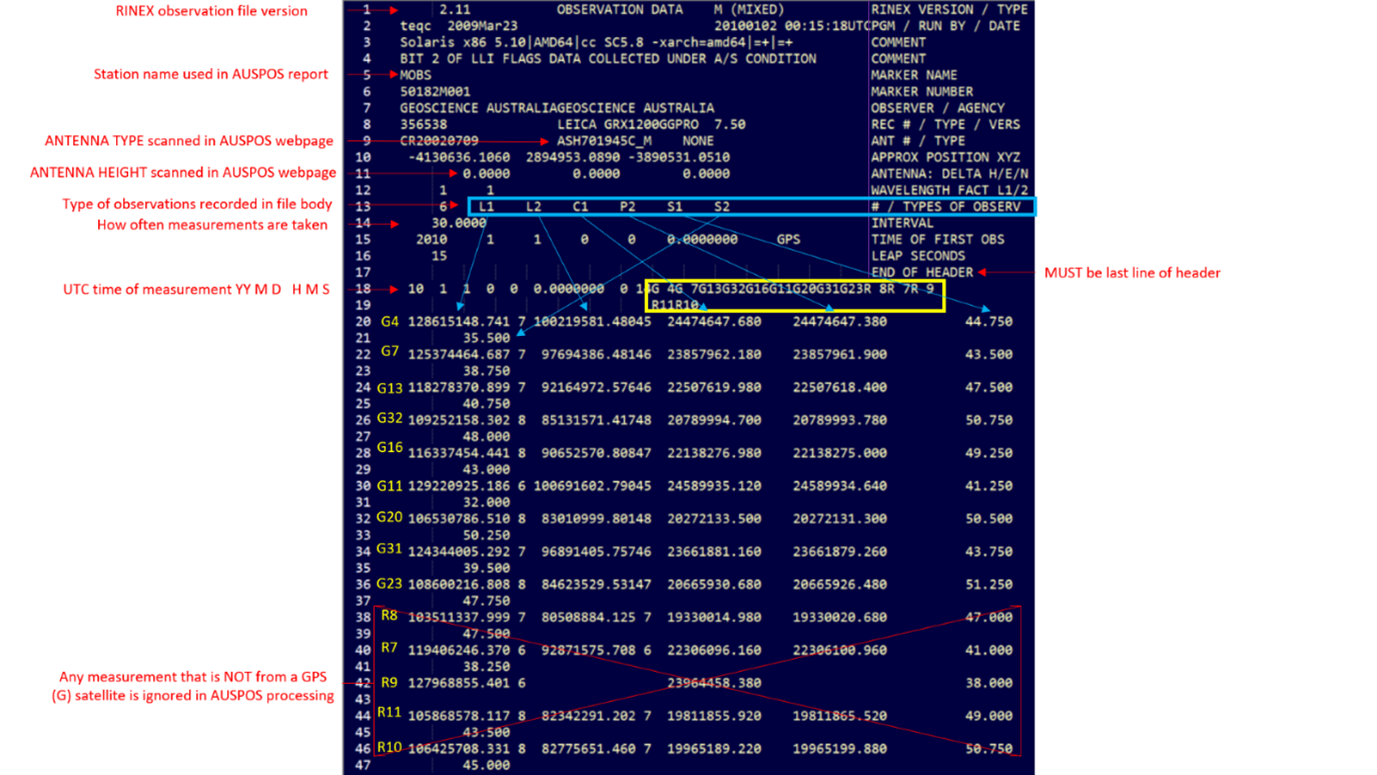
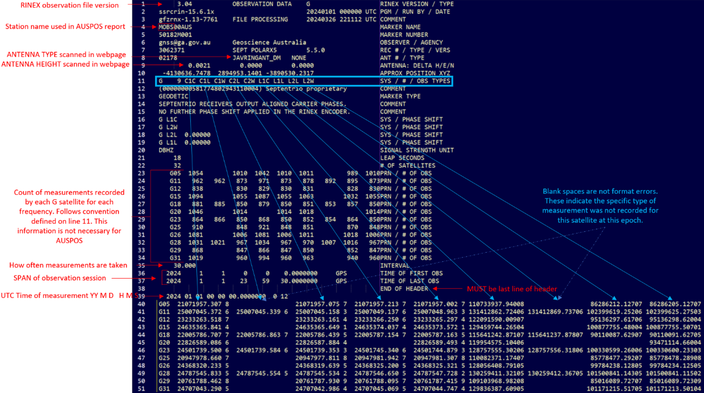
Question 4.7 - What are examples of a RINEX 2 and RINEX 3 (4) files?
Below are examples of a RINEX v2.11 and RINEX v3.05 header and beginning of the observation records:
Question 5.1 - How do I read the processing report?
The processing report is provided in Adobe PDF format.
Question 5.2 - What parts of the report should I check carefully?
It is recommended that you read the whole report thoroughly to familiarise yourself with the AUSPOS process. The important quality statistics related to your processing job are located in Sections 3-5 of the AUSPOS Report. This includes information such as the Coordinate Precision and Ambiguity Resolution.
Question 5.3 - What are the 'Derived AHD' and 'Derived Above Geoid' heights?
In the GDA section of the AUSPOS report, the user is supplied with a 'Derived AHD' height. This is a height computed using AUSGeoid2020 model. The offset between the ellipsoid and AHD is computed using Geoscience Australia's AUSGeoid2020 product and subtracted from the ellipsoidal height providing the user with a Derived AHD height. The AUSGeoid2020 model of ellipsoid to AHD separation values only extends 33 km offshore. Between 33 km and 50 km offshore, the AUSGeoid2020 ellipsoid to AHD separation values are linearly blended with Gaussian weighting with the DTU15 Mean Sea Surface model. The closer to shore, the higher the weighting of AUSGeoid2020 values. From 50 km outwards, the model is only the DTU15 Mean Sea Surface model.
In the ITRF section of the AUSPOS report, the user is supplied with a 'Derived Above Geoid' height. This is a height relative to the Earth Geopotential Model 2008 (EGM2008).
Question 5.4 - The report provides GDA and ITRF coordinates, but what about WGS84 coordinates?
ITRF and WGS84 are generally considered to be equivalent (to within 0.1 m).
Further information
Question 6.1 - Why do I have to specify the GPS antenna?
To achieve the highest quality processing results, attention needs to be paid to the type of antenna used. Using the incorrect antenna type can introduce significant bias (greater than 10 cm in the vertical component) and noise into the computed coordinates.
The actual observation point on a GPS antenna is called the electrical phase centre. The location of this phase centre is represented by a mean constant offset from the physical point on a GPS antenna, known as the Antenna Reference Point (ARP), and an additional variable offset that is dependent on the transmitting satellite's elevation.
The properties of the electrical phase centre are different for every type of antenna. Importantly, the electrical phase centre can be modelled provided you know the antenna type.
Question 6.2 - What is the antenna height?
The antenna height is the vertical distance from the ground mark to the Antenna Reference Point (ARP). The ARP is the physical point on a GPS antenna that measurements are typically reduced to. The ARP varies between antenna types. As a WARNING, the ARP is rarely the top of the Antenna Ground Plane. The ARP height should NOT be confused with slant and other instrument height measurements commonly used in GPS processing.
Question 6.3 - What type of GPS antenna do I have?
AUSPOS uses the IGS antenna naming convention. The IGS - Naming Convention Document provides more information.
Further information regarding the specifications of antennas can be found on the National Geodetic Survey (NGS) antenna calibration website.
Question 6.4 - What happens if I choose the DEFAULT(NONE) antenna?
If you choose the DEFAULT(NONE) antenna type; no antenna phase centre model or offset is applied.
If you set the antenna height to 0.0000 m and choose an antenna type, then the position of the ARP is computed.